
Welding flaws in ISO 3183 L320 pipe are a major quality issue for pipeline projects in oil and gas transport, water supply systems, and building offshore platforms. These flaws, which include holes, cracks, and partial fusion, can weaken the structure, lower its ability to hold pressure, and raise the cost of its life by causing it to fail early. When procurement managers, pipeline engineers, and quality inspection teams know how to spot common welding flaws in ISO 3183 L320 pipe, what causes them, and how to stop them, they can make decisions that protect project timelines and operational reliability. You can use the information in this piece, along with field knowledge and foreign guidelines, to help you figure out how to get consistent weld quality in medium-pressure pipeline applications.
|
|
|
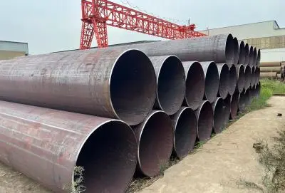
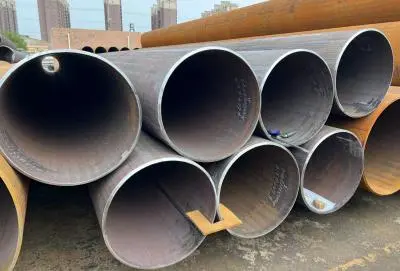
Understanding ISO 3183 L320 Pipe Welding and Its Challenges
As a specialized medium-pressure gathering grade, ISO 3183 L320 pipe is used in the transmission system for oil and natural gas. This linepipe grade has a minimum yield strength of 320 MPa and a minimum tensile strength of 435 MPa under PSL1 standards. It was made so that project costs can be balanced with a thinner wall. For projects that need higher quality control, PSL2 versions offer yield ranges from 320 to 525 MPa and tensile ranges from 435 to 655 MPa. They also have to go through required impact testing to make sure they are tough enough to break at certain temperatures.
Material Composition and Weldability Considerations
The chemicals that make up ISO 3183 L320 pipe have a direct effect on how it welds and how easily it breaks. Manganese content can go as high as 1.30 percent, and niobium or titanium can be added as a microalloy to improve the grain structure and make the metal stronger and tougher at low temperatures. This metal design makes things work better in relatively cold places, which is important for onshore pipes in northern areas where it gets mildly below zero. But these alloying elements also change the carbon equivalent (CEQ), which is usually kept below 0.43 to make the metal easier to weld and stop it from cracking when it's cold during field welding.
Shielded Metal Arc Welding (SMAW) is often used by workers to join ISO 3183 L320 pipes in the field. Gas Tungsten Arc Welding (GTAW) is used for root passes that need precise control, and Submerged Arc Welding (SAW) is used for mill-applied longitudinal seams in LSAW pipe production. To get good penetration, fusion, and heat input control while reducing thermal distortion and residual stresses, each method needs careful parameter selection.
Critical Applications Demanding Defect-Free Welds
The main places where the quality of the weld directly affects operating safety are medium-pressure gathering trunklines and wellhead manifold systems. Medium-pressure natural gas transportation pipes in the region rely on consistent joint integrity to keep leaks from happening in populated areas. The higher pressure rating compared to the L290 grade lets engineers select thinner wall thickness, which lowers the weight of the pipe and the cost of installation. However, this design efficiency leaves less room for weld flaws that could cause cracks to spread when pressure loads change over time.
Common Welding Defects in ISO 3183 L320 Pipes – Identification and Causes
Welding flaws are very dangerous in pipeline uses because they can cause catastrophic breakdowns, environmental damage, and expensive project delays. Quality control teams can take specific steps to fix problems before pipes are put into service by knowing the types of defects and what causes them.
Porosity and Gas Inclusions
Porosity shows up as round or long holes in the welded metal. This happens because gas gets trapped during solidification. In ISO 3183 L320 pipe welding, moisture on the pipe surface or the electrode layer is often to blame. This causes hydrogen gas to form and get stuck in the molten joint pool. If there isn't enough protective gas during GTAW operations, nitrogen and oxygen from the air can react with the metal being welded, making breaks that can be seen on an x-ray. This problem is made worse by wind interference during outdoor field welding, which breaks down gas shields and needs safety steps like windbreaks or changes to gas flow rates.
Cracking: Cold, Hot, and Hydrogen-Induced
Cracking is the biggest threat to the safety of a pipeline because it can spread so quickly. Cold cracking usually happens hours or days after welding. It's caused by leftover tensile loads, hydrogen embrittlement, and a microstructure that is easily damaged. The controlled carbon counterpart in ISO 3183 L320 pipe material helps lower this risk, but restricted joints can still crack if they are heated incorrectly or cooled too quickly. When sulfur or phosphorus particles build up along grain boundaries, hot cracking happens during the solidification of the weld. It usually shows up as centerline cracks in the weld bead. Pay extra attention to hydrogen-induced cracking in sour service settings, where H2S contact can help hydrogen absorb, which is why it's important to store electrodes properly and use low-hydrogen welding methods.
Incomplete Penetration and Lack of Fusion
When the weld metal doesn't go all the way through the pipe wall, leaving an unwelded area at the bottom, this is called incomplete penetration. This problem usually happens because the joint wasn't properly prepared (not enough root hole or too much root face) or there wasn't enough heat applied during root pass welding. Lack of fusion shows up as interfaces between weld beads or between weld metal and base material that aren't joined. This is usually because earlier weld passes weren't cleaned well enough, the electrode angle was off, or the travel speed was too fast, which stops the proper wetting and bonding. Both flaws make stress collection points and possible leak tracks that make it harder to keep the pressure inside.
Undercut and Excessive Reinforcement
Undercut is a groove or dip at the weld's toe that happens when the arc melts the base metal without adding enough filler metal to recover the shape. This flaw is often caused by too much welding current, the wrong electrode angle, or fast trip speed. It lowers the effective wall thickness and makes sharp stress peaks. On the other hand, too much support, like a weld shape that is too convex, makes the structure heavier, makes it harder to coat, and can trap water or contaminants under the coatings. Even though it's not as bad as undercut, too much support could mean bad welding technique and should be looked at closely during quality checks.
Understanding these common types of defects and how they happen is the first step in coming up with effective ways to keep the quality of the weld high during the manufacturing and building phases.
Best Practices and Principles for Preventing Welding Defects in ISO 3183 L320 Pipes
Repairing something is still more expensive than preventing it, so proactive quality assurance is a must for pipeline welding activities. A planned method that includes handling materials, choosing parameters, and proof testing lowers the chance of defects happening and keeps projects on schedule.
Pre-Welding Preparation and Material Handling
Storing ISO 3183 L320 pipe and supplies correctly is the first step in a thorough pre-welding preparation. Pipes should be kept off the ground on racks that keep water and dirt from building up. Before welding, the sides of the joints need to be mechanically cleaned to get rid of mill scale, rust, oil, and other things that could cause the joints to become porous or not fuse together properly. The measurements of the bevels must match the approved welding process, and the root face, root opening, and bevel angle must be the same at all joints. Low-hydrogen electrodes need to be stored in hot ovens under strict conditions so that they don't absorb water. Shielding gases should also be checked to make sure they are pure and have the right mix of chemicals.
Optimizing Welding Parameters for L320 Material
When choosing parameters, the mechanical properties of ISO 3183 L320 pipe grade material must be taken into account. When the temperature outside drops below 0°C or when the pipe wall thickness is more than 25 mm, the preheat temperature becomes very important. Usually, preheat temperatures between 50 and 100°C help slow down cooling and stop cold cracking. Heat input control makes sure that there is enough penetration and fusion without too much grain growth or heat distortion. Typical amounts are between 0.8 and 2.5 kJ/mm, based on the thickness of the pipe and the welding process. Interpass temperature limits, which are usually set between 100°C and 250°C, stop both too much heat buildup that could change the mechanical qualities and too fast cooling that makes the material harder and more likely to crack. Travel speed changes the shape of the beads and how fast they cool, so they need to be calibrated to get smooth, even weld profiles without undercutting or too much strengthening.
Post-Weld Heat Treatment and Stress Relief
Post-weld heat treatment (PWHT) is used for more than one thing when making pipelines. Stress reduction treatments, which are usually done at 580–650°C for one hour for every inch of wall thickness, lower the tensile loads that are still there and could cause cracks to form later. Normalization techniques even out the microstructure after welding. This is especially important when multiple repair passes or too much heat have caused differences in hardness or stiffness in different areas. PWHT isn't always required for ISO 3183 L320 pipe according to PSL1 standards, but it gives you extra peace of mind for important jobs or when working in bad service settings where stress corrosion cracking is more likely to happen.
Non-Destructive Testing and Quality Verification
Non-destructive testing (NDT) methods check the quality of the weld objectively without hurting the pipe. Using X-ray or gamma-ray sources for radiographic testing (RT) shows internal flaws like porosity, slag inclusions, and lack of entry, as described in ISO 3183 or project requirements. Ultrasonic testing (UT) is a compact way to find flaws on a flat surface, like cracks and missing fusion. It is especially useful for checking joints in the field, where imaging access may be limited. Magnetic particle inspection (MPI) finds surface-breaking and near-surface cracks in ferromagnetic materials quickly, before pipes are put into service. Liquid penetrant testing (PT) is used in addition to MPI to find small surface cracks. When these NDT methods are used with eye inspection and dimensional verification, they make multiple quality gates that catch flaws before they become costly fails.
The prevention framework is finished with welder training and process evaluation. Certified welders show they are skilled by passing standardized tests, and qualified welding processes give written instructions that combine quality needs with efficiency needs. Regular exams and programs for ongoing growth keep performance high over long project periods.
Conclusion
Welding flaws in ISO 3183 L320 pipe can be fixed by using the right materials, making sure the quality is high, and working with makers who have a lot of experience. Knowing the different kinds of defects—porosity, cracking, incomplete penetration, and undercut—allows for tailored prevention plans that include careful preparation, the best welding settings, heat treatment after the weld, and full NDT verification. The ISO 3183 L320 pipe grade is the best combination of being able to be welded and having good mechanical properties for medium-pressure transmission and gathering uses. It makes construction easier while still being reliable in the long run. Finding qualified sources with well-documented quality systems and expert support skills lowers risk and helps projects succeed from the beginning to the end of their operational lives.
FAQ
What makes L320 pipe welds have holes in them?
Porosity happens when gas gets trapped during the solidification of a weld. This can happen because of contaminated pipe surfaces, wet electrodes, not enough protecting gas, or wind interference when welding outside. Keeping materials in the right way, preparing electrodes, and managing shielding gases properly can stop most porosity flaws.
What's the difference between PSL1 and PSL2 for ISO 3183 L320 pipe?
For general uses, PSL1 offers normal grade that meets basic chemical and mechanical requirements. PSL2 requires higher quality, with requirements like required impact testing, tighter chemical composition limits, and full tracking. This makes it suitable for use in critical or sour service situations.
Can ISO 3183 L320 pipe be used in places that are cold?
It works well in relatively cold areas with mild subzero temperatures when ISO 3183 L320 pipe is delivered in normalized or normalized plus tempered (N/M) conditions. Up to 1.30 percent manganese and possible niobium or titanium additions make the steel tougher at low temperatures, which helps it work in northern pipeline routes.
What NDT methods check the quality of the weld in L320 pipe?
Radiographic testing (RT) finds flaws inside the body, such as holes and a lack of access. Ultrasonic testing (UT) finds flaws on a flat surface, like cracks and missing fusion. Magnetic particle inspection (MPI) finds cracks on the surface and close to the surface. When used with eye inspection, these ways give a full picture of quality.
Partner with Longma Group for Defect-Free ISO 3183 L320 Pipe Solutions
Longma Group is ready to help you with your next pipeline project by providing you with high-quality ISO 3183 L320 pipe that is made to strict international standards. We are a reliable maker and provider with more than 20 years of experience making high-quality products. We offer consistent quality that is backed by full certifications and documentation packages. Our technical team gives advice on how to weld and how to avoid defects, which speeds up building and cuts down on quality-related delays. Get in touch with us at info@longma-group.com to talk about your project needs and find out how our ISO 3183 L320 pipe for sale can improve the quality of your pipeline while also making the project more cost-effective.